Follow the daily solar path.
One dedicated row drive controls east–west tracking.

MODMEC TECHNOLOGY
A dual-axis tracker built on a single-axis row architecture. The second axis improves orientation to direct sunlight throughout the day, including solar noon. Four modules fit on each frame; the entire row shares two drives.
See how it moves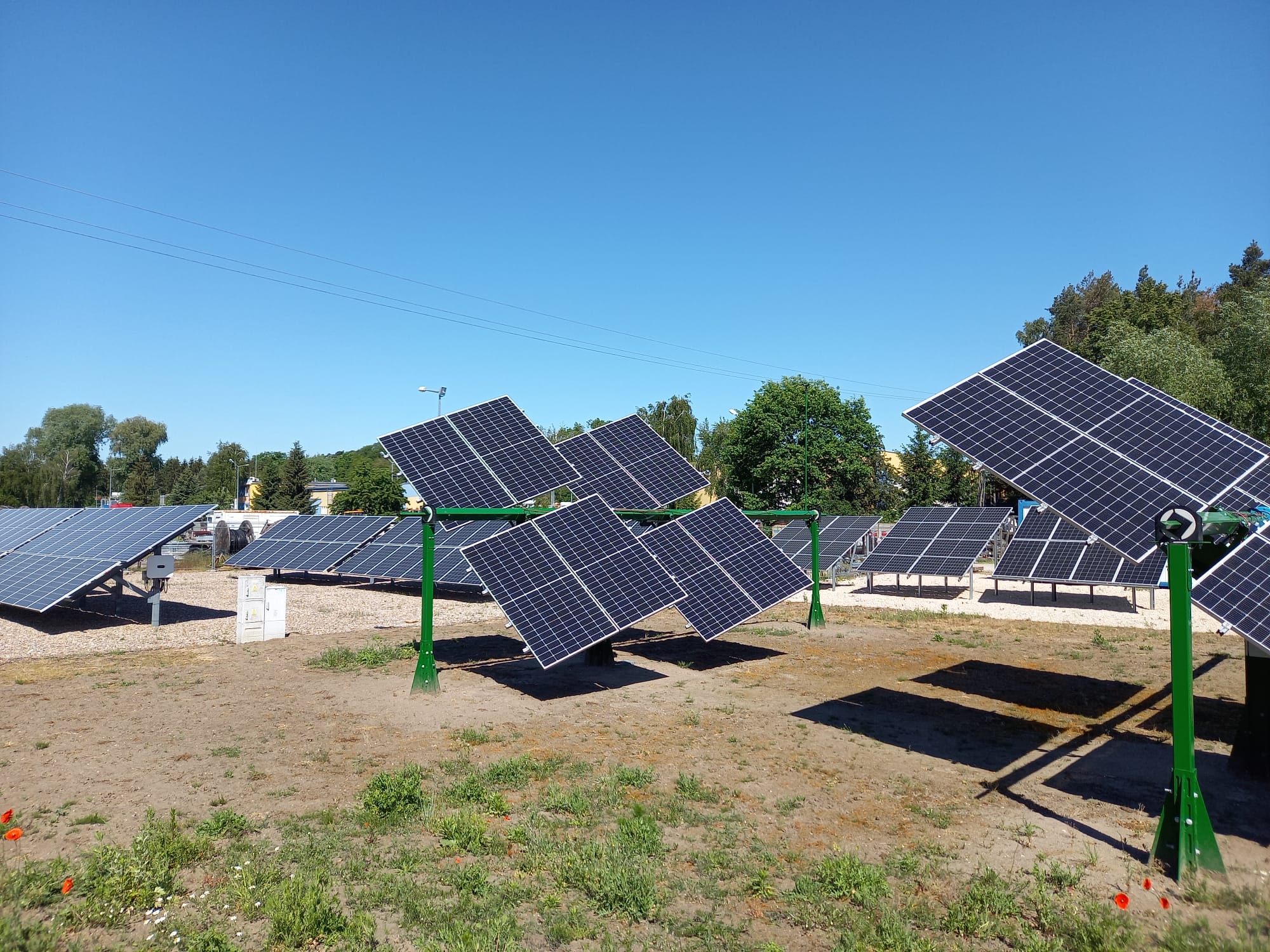
One 90 m (295.3 ft) row accommodates a maximum of 30 frames: 30 frames × 4 modules = 120 modules, controlled by two drives.
01 / THE BUILDING BLOCK
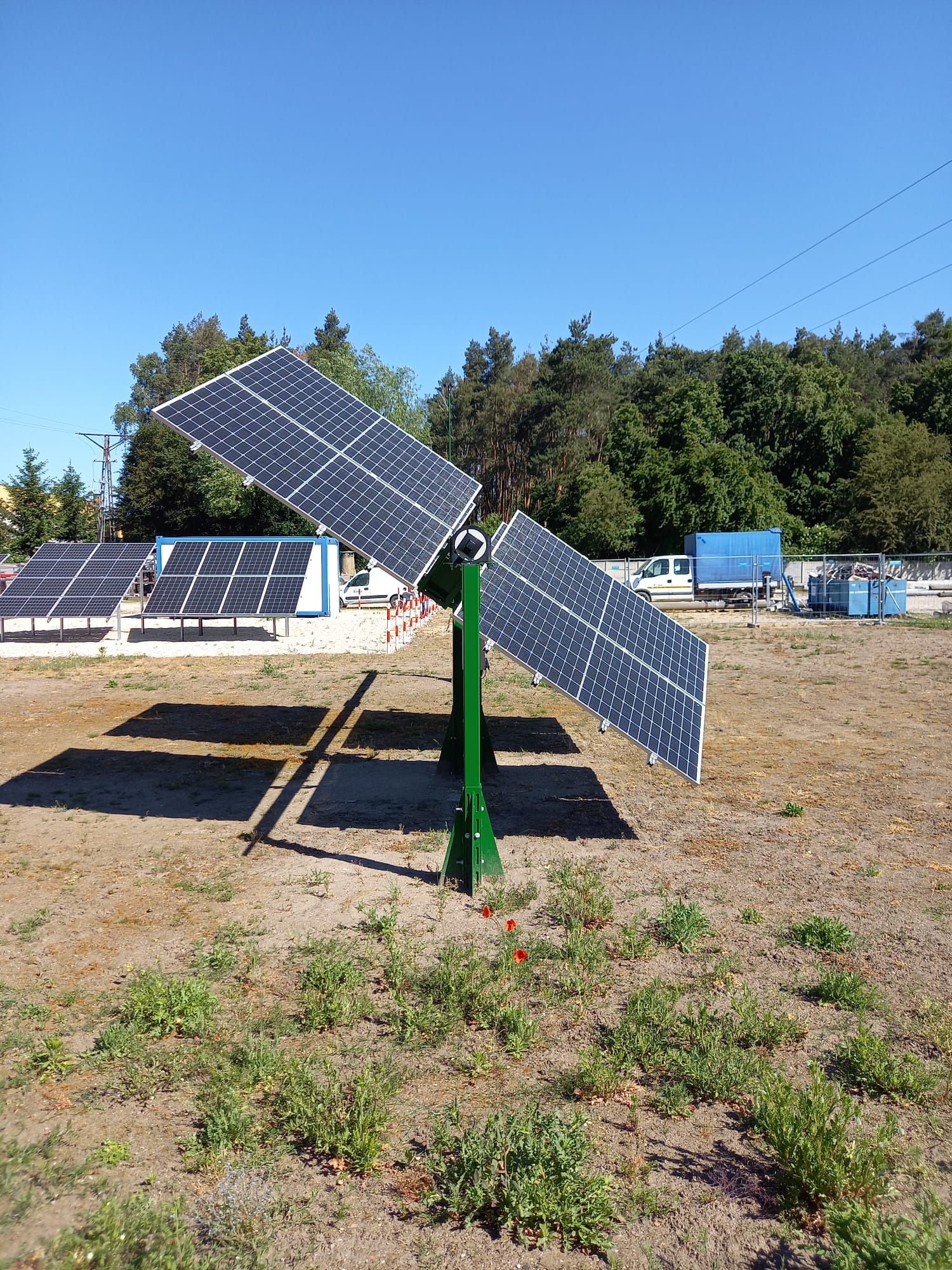
Each frame carries four PV modules. The frame repeats along a shared row structure, so a small prototype and a longer project row use the same architectural principle.
The photographed field prototype uses two frames and eight modules. It shows the building block; the commercial design extends that structure along the row.
Module dimensions and the final frame configuration are selected during project engineering.
02 / HOW MODMEC MOVES
The single-axis row architecture is extended with a second controlled axis. Two drives coordinate the entire row: one for east–west (E–W) tracking and one for south–north (S–N) adjustment.
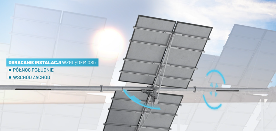
One dedicated row drive controls east–west tracking.
The second dedicated row drive adjusts module orientation as solar elevation changes through the day and across seasons.
Both drives serve the entire 90 m (295.3 ft) row, carrying up to 120 modules. Each frame shares the row drive system.
The two-axis design aims to keep the module surface perpendicular to direct sunlight throughout the day. The second correction also matters at solar noon: a conventional horizontal, north–south single-axis tracker is then approximately flat, while the sun may still be well below the zenith. MODMEC can adjust the second axis to improve that direct-beam orientation. Site geometry and operating limits determine the achievable position.
03 / FROM FRAME TO FIELD
A 90 m (295.3 ft) row accommodates a maximum of 30 frames. With four modules on each frame, one row / tracker carries up to 120 modules and uses just two drives—one for E–W and one for S–N. The 198 kWp example uses three such rows.
Tested in Poland at 51.87°N. The row arrangement shown here was tested in Polish field prototypes at a northern latitude of 51.87°. The drawing extends that arrangement to the 90 m pilot row configuration.
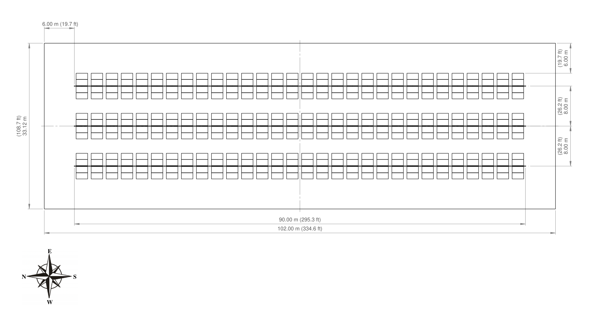
A concept layout, not a construction drawing. Row spacing, setbacks, access, shading, movement clearance and equipment areas require site-specific review.
View the layout PDF (m / ft)04 / SOLAR + LOAD + STORAGE
Second-axis correction is designed to strengthen direct solar capture in the morning, at solar noon and in late afternoon. The resulting PV profile can support demand and charge BESS across a longer window, allowing stored energy to be used later.
Additional PV capture can increase delivery to the load or grid and create surplus for earlier BESS charging.
PV · LOAD / GRID + BESSUse maximum feasible PV production to serve demand within the connection limit. Route available surplus to BESS, subject to charging power and remaining capacity.
PV · LOAD / GRID + BESSAdditional late-day solar can serve the load or grid and, where surplus remains, continue charging BESS—even during hours when a single-axis comparison may already need battery support.
PV · DELIVERY / CONTINUED CHARGINGEarlier or longer charging and later discharge can leave more stored energy available for evening and overnight demand. Coverage depends on the battery size, losses, dispatch and load.
BESS · LOAD / GRIDMODMEC strengthens generation. BESS shifts energy in time.
SMART WATTS · IN DEVELOPMENT
Smart Watts is being developed to use weather forecasts, site demand, battery state and point-of-interconnection limits to guide operating decisions. Storage size and savings must be evaluated for the specific project.
Use more solar directly throughout the operating day, including midday. Evaluate earlier and continued BESS charging, a later start of discharge and stored energy available for evening and overnight demand. Continuous supply still requires a project-specific combination of PV, storage, the grid or other generation.
Explore the solar + storage scenario05 / PRACTICAL DEPLOYMENT
The deployment strategy combines repeated hardware, factory preparation and local fabrication and installation partners.
Planned preassembly, including DC wiring, aims to reduce field assembly and wiring work. U.S. labor and cost outcomes remain to be measured.
Project design must provide access to drives, electrical equipment and module frames for inspection, replacement and routine service.
Operating limits and protective positions require engineering for local wind, weather, ground conditions and the actual movement envelope.
06 / FIELD HARDWARE & NEXT STEPS
Field prototypes of approximately 7 kW and 11 kW have operated in Poland. They provide physical evidence of the architecture and tracker motion.
The U.S. pilot is intended to measure hourly generation, availability, drive consumption, installation effort, stow behavior and maintenance requirements. Those measurements will support project-specific performance and cost comparisons.
Explore prototype evidence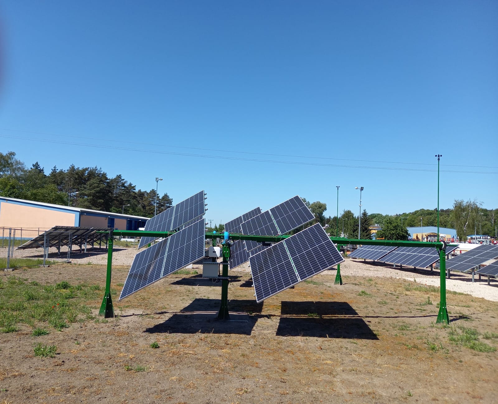
BRING THE PROJECT QUESTION
Start with location, load, land, storage and connection limits.
Request a Generation ProfileDiscuss the technology